TM 5-3610-295-13&P-1
4-34. BLACKOUT WARNING ASSEMBLY. - Continued
b. Replace. - Continued
(2) Warning Buzzer.
(a)
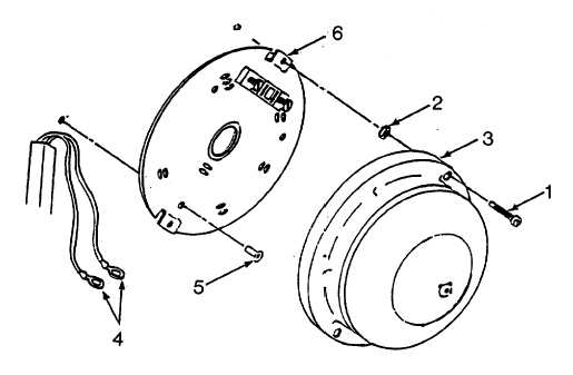
Remove warning buzzer screws (1, Figure 4-44) and lockwashers (2).
(b)
Remove buzzer (3).
(c)
Tag and disconnect electrical wires (4).
(d)
Remove rivets (5) by drilling or chiseling off heads.
(e)
Remove buzzer base (6).
(f)
Position buzzer base (6) of warning buzzer on wall and secure with rivets (5).
(g)
Connect electrical wires (4) to terminals and remove tags.
(h) Position buzzer (3) on base and secure with screws (1) and lockwashers (2).
Figure 4-44. Blackout Warning Assembly Buzzer
c
Repair. Repair for the blackout warning assembly consists of replacing components.
4-106