TM 5-3610-295-13&P-1
4-34. BLACKOUT WARNING ASSEMBLY. - Continued
b. Replace. - Continued
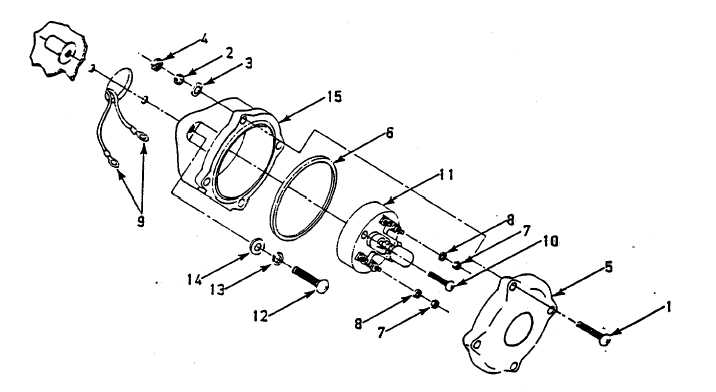
(i) Secure switch (11) to housing (15) with screw (10).
(j) Connect electrical wires (9), secure with nuts (7) and lockwashers (8), and remove tags.
(k) Position switch cover (5) and gasket (6) on housing and secure with screws (1), flat washers (3),
lockwashers (2), and nuts (4).
Figure 4-43. Blackout Warning Assembly
4-105