TM 11-6780-225-12
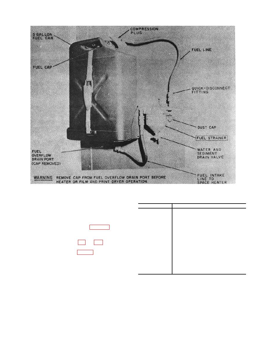
Figure 1-13. 5-gallon fuel supply installation.
lake or stream, or from the water tank in the darkroom.
Circuit breaker
Controls
Water from the water tank can be channeled either to
1 .....................
Air conditioner No. 1.
the processing sink or the processing unit, or both.
2 .....................
Air conditioner No. 2.
3 .....................
c. Intercom and Wire Raceway System.
The
4 .....................
Immersion heater, refrigerator,
intercom and wire raceway system (fig. 1-18) houses
intercom, and exhaust fan,
110-volt and intercommunication wiring to each
5 .....................
Water heater.
6 .....................
Safelights.
compartment in the darkroom and communication to the
7 .....................
Space heater and film and print
drier exhaust fans.
into the darkroom through the circuit breaker panel
8 .....................
Print processors and enlargers.
located in the aft compartment (fig. 5-2), and distributed
9 .....................
Processing unit.
to 11 circuits. The thermostat for air conditioner No. 2,
10 ...................
Water pump.
the space heater, and film and print drying cabinets are
11 ...................
Compartment lighting.
included in this system. The circuit breakers controlling
12 ...................
(Spare)
13 ...................
All power to darkroom.
the circuits of the darkroom are given below.
NOTE
The circuit breaker number designates
the circuit number which it controls .
1-15


