
TM 11-6720-242-35
TM 116720-242-35
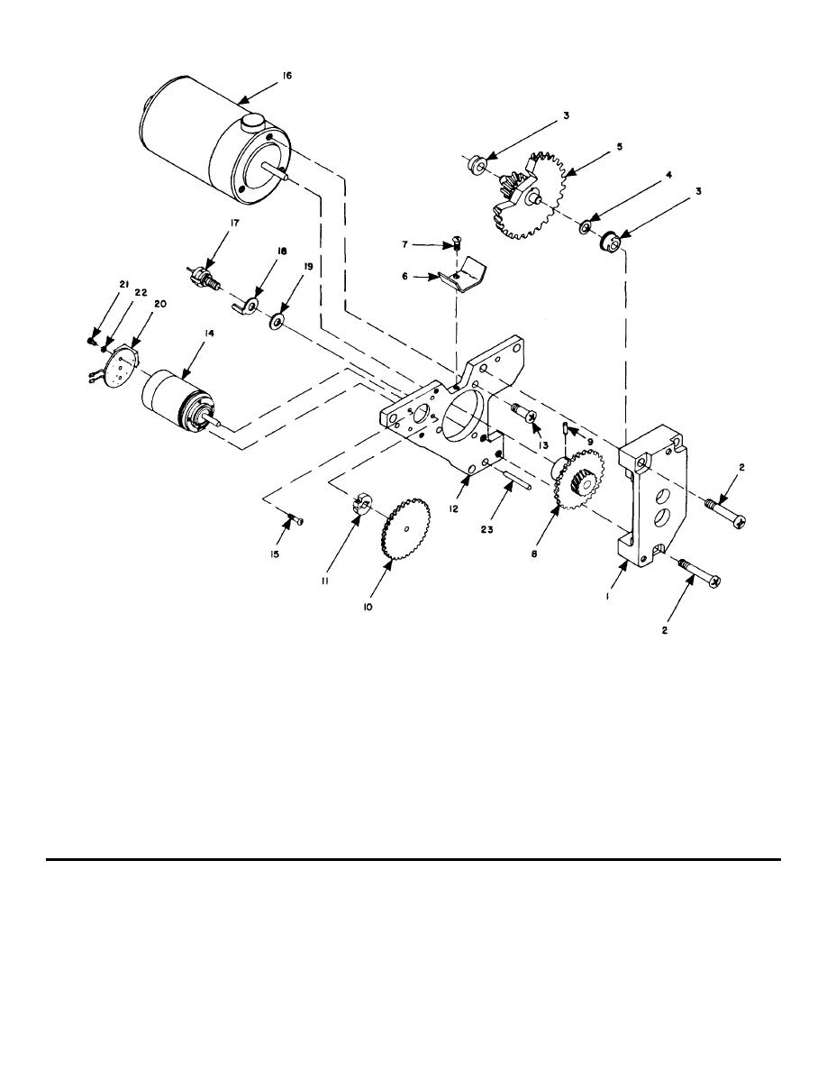
1
Support (MP212)
13
Screw (H153-155)
2
Screw (H148-149)
14
Tachometer (G1)
3
Bearing (MP140-141)
15
Screw (H132-437)
4
Shim (IP365-368)
16
Motor (B1)
5
Gear assembly (MP197)
17
Diode (CR2)
6
Guide (MP200)
18
Terminal (P/O CR2)
7
Screw (H131)
19
Fiber washer (P/O CR2)
8
Gear assembly (M1P214)
20
Circuit board assembly (1AlA4)
9
Pin (MP257)
21
Screw (H138-139)
10
Gear (MP198)
22
Washer (H1140-141)
11
Clamp (MP172)
23
Pin (MP812)
12
Plate (MP211)
Figure 3-7. Motor, gear, and tachometer-generator, exploded view.
NOTE
(4) The removal procedure on the left side of
When replacing the C washer (102)
the pressure roller assembly is identical to that of step
be sure that the flat side of the
(3) except that the spacer (105) is not included.
washer is in contact with the
(5) The pressure roller assembly can now be
removed.
magazine
housing.
b. Replacement.
3-30
