Home
Download PDF
Order CD-ROM
Order in Print
Figure 2-8. Conversion of V/H signal to Intervalometer pulse.
Functioning of Power Supply
TM-11-6720-242-35 Camera Still Picture KA-60C Manual
Page Navigation
13
14
15
16
17
18
19
20
21
22
23
TM
11-6720-242-35
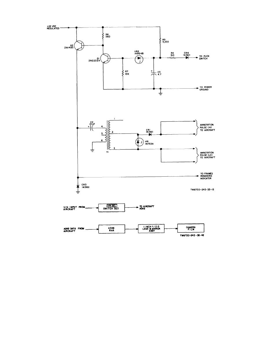
Figure
2-10.
Annotation
pulse
circuit,
schematic
diagram.
Figure
2-11.
Auxiliary
data
annotation
system
(adas),
block
diagram.
2-17