
TM 11-6720-242-35
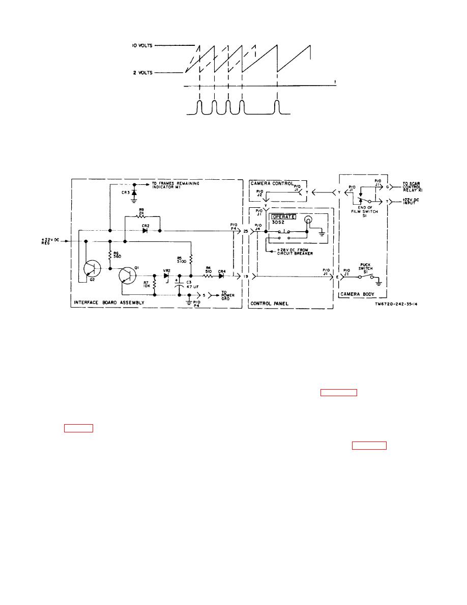
THE DOTTED LINE WAVEFORM IS A LARGE V/H INPUT
AND THE SOLID LINE WAVEFORM A SMALLER V/H INPUT TM6T--242-3-37]
Figure 2-8. Conversion of V/H signal to Intervalometer pulse.
Figure 2-9. Fail safe and frames remaining circuits, schematic diagram.
film or as a result of film breakage. In its actuated
(2) Autocycle mode. When the speed and
position, the switch applies +22 vdc regulated to the
height of the aircraft is such that the V/H signal causes
scan control and control board circuits, closes the
the camera to cycle at one cycle per second, the
interlock circuit and camera operation results. In its off
camera automatically switches to the autocycle mode of
position the interlock circuit is open and camera
operation. The V/H signal is amplified by amplifier
operation ceases, also voltage is applied to the fail safe
2A4AR1, the voltage detector zener diodes VR4 and
circuit which causes the control panel OPERATE lamp
VR5 cause transistor Q5 to turn on and energize relay
to illuminate steadily (para 2-12).
2A4K3 thus placing the camera in the autocycle mode
of operation. In the autocycle mode the cycling rate is
2-16. Functioning of Power Supply
from one cycle to eight and one-half cycles per second.
b. End of Film Switch. The end of film switch
a. Primary power of 115 vac, 400 Hz, 28 vdc, and
lAIS1 (84, fig. 3-3 (3)) is located in the aec assembly.
5 vdc is furnished from aircraft sources and applied to
The switch is on when its actuating shaft is held in a
the camera through filter 3FL1 and POWER switch 3S1
depressed position by the pressure of the film passing
located on the control panel (fig. 6-12). The 115 vac,
over it. The shaft is released and turns the switch off at
400 Hz input and the +28 vdc input are connected to
the end of
respective circuit
2-16
