
will permit, and unscrew the two terminal screws that hold
the lead clips to the connector. Remove the connector.
(4) Replace the connector by reversing the disassembly instruc-
tions given in (1) through (3) above.
i. Rear Surface Mirror and Mirror Support.
(1) Remove the projection-stage plate glass and the Fresnel con-
denser lens (b above).
(2) Remove the two screws that hold the mirror retaining strip in
place at the top front of the housing (fig. 26) and remove the
retaining strip. Slide the mirror carefully up and out of the
housing.
(3) To remove the mirror support, first unscrew and remove the
two screws that hold the support in place on the sides of the
housing. Then unscrew and remove the two screws that hold
the support in place at the top front of the housing. L i f t
the support out of the housing.
(4) To replace the rear surface mirror and the mirror support,
reverse the disassembly instructions given in (1) through
(3) above. Whenever the mirror support is removed, the
mirror must be realined (par. 59d ( 2 ) ) .
it in place at the inner corner of the housing, and pull the glide from
the housing. To replace a glide, slide the glide shaft into the hole at
the corner of the projector housing, and replace the nut on the shaft
from inside the housing.
k. Support-Post Clamping Knob. To remove the support-poet
clamping knob, use an Allen wrench to loosen the two setscrews in
the collar of the knob. Then pull the knob from the shaft. To
replace the knob, push it on the shaft, and then tighten the two
setscrews.
PH-637A/PFP, first raise the housing cover until it is retained in the
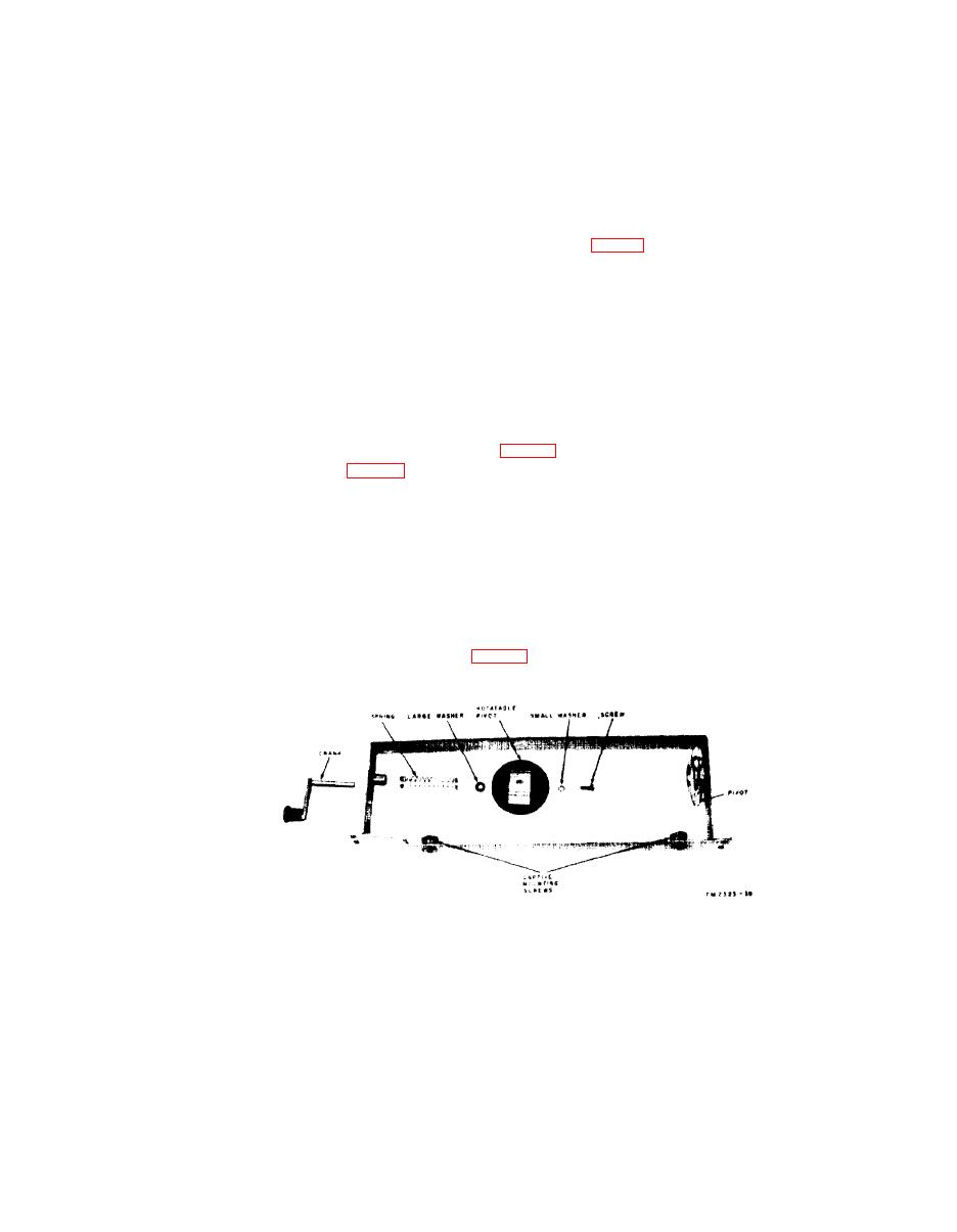
Figure 32. Roll attachment crank disassembled.
59
TAGO 4738B
