
49.7. Drivebelt Tension Adjustment
(fig. 23.4)
If the polarizer does not rotate or operates erratically with a tend-
ency to slippage, adjust the drivebelt tension as follows :
Q. Remove the top cover (12) as instructed in paragraph 49.6b (2)
and (4).
b. Loosen the nylon screws (23) that pass through the slotted holes
of the base plate assembly (35) into the motor (22). The motor can
now be shifted towards or away from the polarizer assembly (21).
c. To tighten the drivebelt (18), shift the motor away from the
polarizer assembly. Tighten the nylon screws (23) and operate the
spinner. If there is evidence of slippage or binding, loosen the screws
and shift the motor position again. The desired setting is the mini-
mum tension which permits the rotating polarizer to operate with no
evidence of slippage.
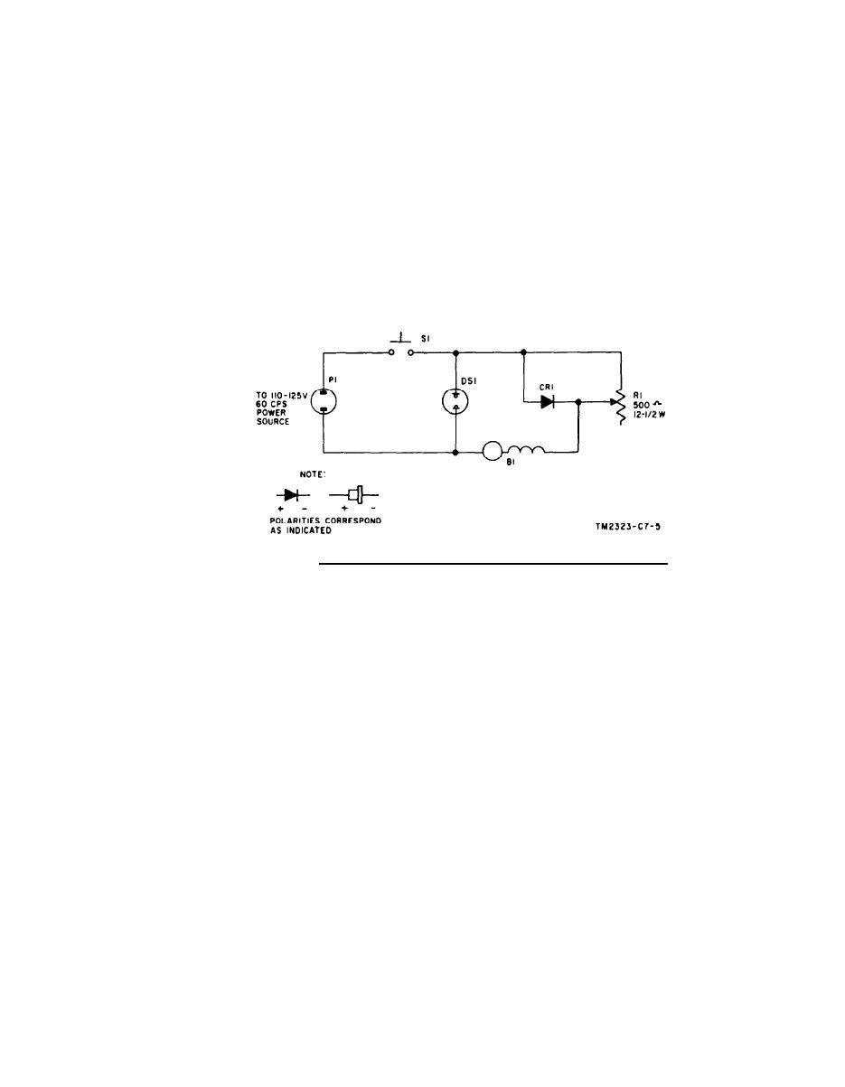
FIGURE 23.5. Spinner, Polarizer BM-34(A), achematic diagram.
21
1
Polarizer assembly (A3)
Bottom cover (A1)
2
Motor (B1)
22
Screw (H1)
Nylon screw (H13)
3
23
Flat washer (H2)
Flat washer (H14)
24
4
Hex. nut (H3)
25
Motor pulley (MP4)
Lockwasher (H4)
5
6
Setscrew (H15)
26
Roll pin (H5)
7
Neon lamp (DS1)
27
Screw (H6)
Clamp (MP5)
8
28
Mounting clamp (MP1)
29
9
Screw (H16)
Spring washer (H7)
Lockwasher (H17)
30
10
Retaining ring (H8)
11
Power cable (W1)
31
Clamp post (MP2)
12
Clamp (MP6)
32
Top cover (A2)
Screw (H18)
33
13
Screw (H9) (5 each)
Lockwasher (H19)
14
34
Flat washer (H10) (5 each)
15
35
Base plate assembly (A4)
Variable resistor (R1)
36
Knob
16
Switch (S1)
17
37
Hex. nut
Diode (CR1)
38
Flat washer
18
Drivbelt (MP3)
19
39
Threaded collar
Retaining ring (H11) (3 each)
Hex. nut
40
20
Roller (H12) (3 each)
Figure 23.4 Spinner, Polarizer BM-34(A), exploded view.
9
TAGO 763B
