TM 10-3610-203-14
(c) Using a suitable meter or test light, check for continuity at wire connections when blackout warning switch is
depressed.
(2) Removal. Remove blackout warning buzzer as follows:
(a) Position blackout buzzer circuit breaker in main power service box to off.
(b) Tag and disconnect two wires at the buzzer base.
(c) Remove the screws which attach the buzzer base to the outlet box on the shelter wall and remove the base.
(3) Repair. Repair of the blackout warning buzzer consists of replacement.
(4) Installation. Install the blackout buzzer as follows:
(a) Position replacement buzzer base on the outlet box and secure with attaching screws.
(b) Connect two wires at the buzzer base and remove tags.
(c) Position the blackout warning buzzer cover on the buzzer base and secure with attaching screws.
(d) Position blackout buzzer circuit breaker in main power service box to on.
(e) Depress blackout warning switch and ensure that buzzer operates correctly.
b. Blackout Warning Switch.
(1) Inspection. If the blackout warning buzzer is not activated when the switch is depressed, inspect/test the switch
as follows:
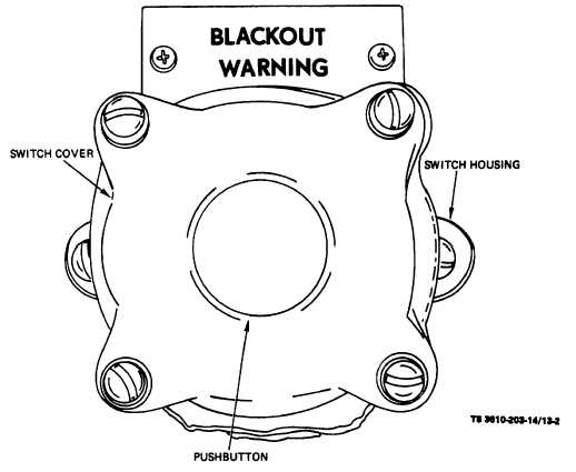
(a) Remove three nuts, lockwashers and bolts that secure the cover to the housing. Loosen the fourth nut and
allow the cover to swing down. (See fig. 13-2).
Figure 13-2. Blackout Warning Switch, Removal and Installation.
13-2