
TM 11-6720-242-35
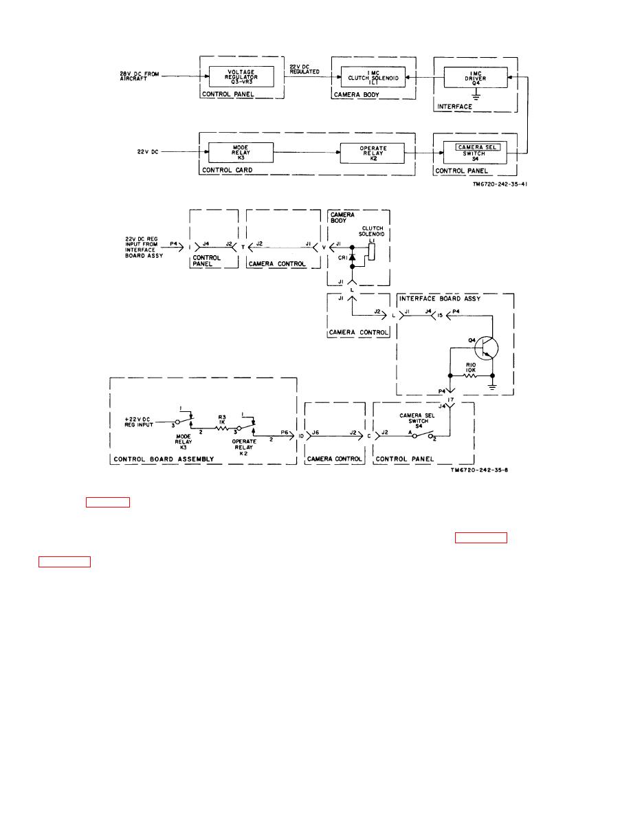
Figure 2-2. Image motion compensation (imc), schematic diagram.
Figure 2-3. Image motion compensation (imc), schematic diagram.
oscillation (para 2-8). The front pinion (15) of idler gear
are all grouped together and mounted on, but
(14) drives the prism gear (21) and rotates the prism
independent of the puck (31) shaft. The capping cam
(22). Pulley (23) rotates pulley (24) via the timing belt
causes the capping blade (34), which is located in the
(25) causing the timing cam (32) and gear (26) to rotate.
aec assembly, to operate (para 2-14). The puck, which
The timing cam makes and breaks the puck switch (33)
rotates continuously, is not involved in the timing
sequence and is driven by the meshing of the puck gear
(28), and the capping cam (29) which
(30) with the idler gear (14).
2-9

