
TM 11-6720-239-35
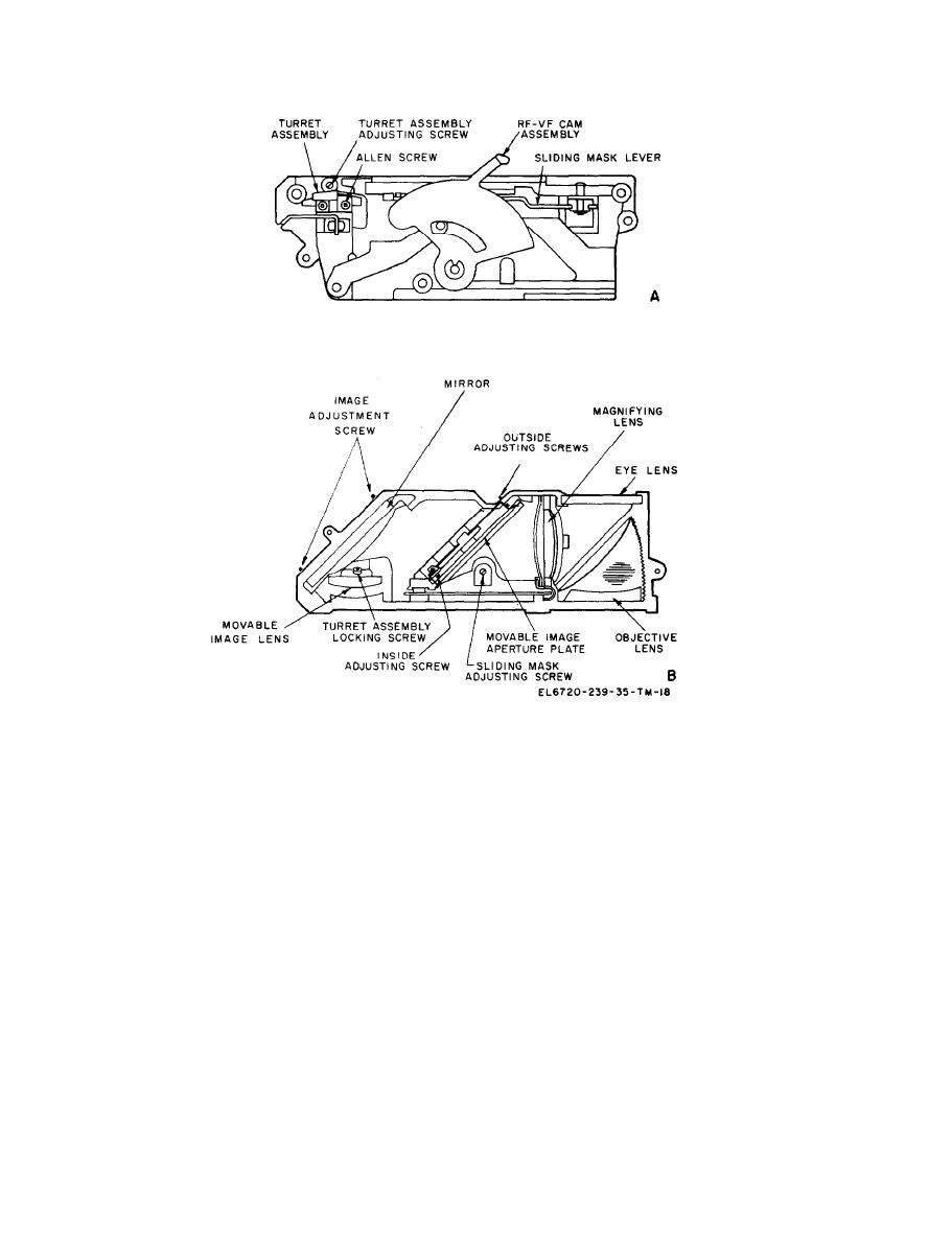
Finder assembly, adjustments.
(3) When gauge is fully depressed, shutter
(3) If further adjustment is required, turn
the right-hand image adjusting screw at the rear
should trip.
(4) Re-cock the shutter. Center the recessed
of the mirror. Turning this screw in will move the
image to the right, and turning screw out will
end of "Go-No-Go" gauge over shutter release
movethe image to the left.
knob.
(5) When gauge is fully depressed, shutter
f. Shellac all lenses, except the mirror, into po-
should not trip.
sition.
c. Installation and Adjustment of Shutter Cable
Release.
(1) Insert shutter release return spring and
Adjustment
shutter release knob into shutter release bushing.
a. General. The shutter release cable must be
(2) Depress shutter release knob until the
the correct length to allow proper tripping action,
bottom edge is even with the top edge of the shut-
without being so long that the shutter release
ter release bezel.
knob can be accidentally tripping.
(3) Position shutter release tip on the oppo-
b. Operational Camera Check.
site end of the cable and crimp in place.
(1) Open camera and cock the shutter.
(4) Insert shutter release cable assembly into
(2) Place the small radial end of "Go-No-Go"
camera body. Shutter cocking arm should be in
the up or uncocked position.
gauge against the shutter release knob.

